


Machinery for Loading
Glass Cutting & Logistic


Reliable processes, good quality, solid profit: LiSEC
solutions provide flat glass processors around t
he world
with security and drive in a challenging environment.
For the last 60 years, we have been wor
king ha
rd to
enable you to sust
ainably boost the efficiency, the
system
availability and the quality output of your flat gla
ss
production process. Thanks to forward-looking thinking,
continuously striving to find the best solution and a gre
at
deal of personal commitment from our employees, we hav
e
grown from a one-man compa
ny to a technology leader.
Our advanced solutions gener
ate a great cost-to-b
enefit
ratio throughout the entire lifecy
cle of your machines and
systems.
Customers around th
e world can benefit from this: be they
experienced manufacturer
s or newcomers to the industry;
from family businesses to industrial glass pr
ocessors.
Three main factor
s are essential for long-term success:
1. Turn Key Solutions
Everything from a single source including soware. Customers be
nefit from the only company in the flat glass machine
industry that can comprehensively plan and de
velop large projects - also thanks to the widest product ra
nge in the industry.
2. Excellent Service
Investment security and the highest availability and productivity enable the la
rge
, global LiSEC service
network. A contact person familiar with the local language
and customs is available close to you.
3. Performance through soware integration
Integration of the production management soware a
nd the machinery control (digitalization/Industry 4.0)
allows top operation and optimization of all integrated machines or whole glass factories.
The benefits:
O
ver 60 years of partnership, pioneering spirit and stability
Investment security due to the size of our company
Leading technology with a high resale va
lue
Great cost-
to-benefit ratio throughout the entir
e system lifecycle
Facts and figures:
1961 founding year
1 strong brand
1,100 employees
Over 20 sites
213 m
illion Euros turnover (2021)
Over 90 % export rate
7 % of turnover for R&D
More than 330 patents
02
03

![[x]](index_htm_files/close.png "Schlie�en")

Ta
b
l
e of Contents

04
05
Li
nes
Combin
ed Line
V
S
L-A laminated gla
ss cu
t
ting sys
tem with
p
o
si
t
ioning s
t
at
ion
p. 10
High-performance syst
em for cutting float
and laminated glass aut
omatically
V
S
L
-
A D
ouble B
r
idge S
ys
tem S
olu
t
ions
p. 12
High-performance machine for cutting
laminated safety glas
s automatically
Float G
la
s
s B
r
ea
kou
t S
ys
tems
p. 14
Machines for Automatic Cutting
and Breaking of Float Glass
S
tand-Alone Machines
Flat Glass Cutting
FLA
T GLA
SS C
UTTI
NG OVERVI
EW
p. 18
D
S
C
-
A
p. 20
High-performance machine for
cutting flat glass aut
omatically
G
F
B
p. 22
Machine for Automatic Flat Glass C
utting
E
S
L
-
RS
p. 24
High-performance machine for
cutting flat glass aut
omatically
Spr
in
t
C
u
t
p. 26
High-performance machine for
cutting flat glass aut
omatically
b
a
se C
U
T
p. 27
Machine for Automatic Float Glass C
utting
Laminated Glass Cutting
LAMI
NA
T
ED GLA
SS C
UTTI
NG OVERVIEW
p. 28
V
S
L-A laminated gla
ss cut
ting sys
tem
wi
t
h p
o
si
t
ioning s
t
a
t
ion
p. 30
System for the aut
omatic cutting
of laminated safety glas
s
V
B laminated gla
ss cut
ting sys
tem
p. 32
System for the semi-aut
omatic cutting
of laminated safety glas
s
Break Out Systems
BREAK-OUT SYST
EM
S OV
ERVIEW
p. 34
A
R
S / TCY
p. 36
Automatic break-out device for trim cuts
T
BX /
T
B
Y
p. 37
Automatic break-out device for sub-plate breaks
T
B
R
p. 38
Automatic break-out device for trim
cuts and sub-plate breaks
T
D
V
p. 39
Horizontal sub-plat
e rotating device, 90°
Glass Loading System
GLA
SS L
OADI
NG OVERVIE
W
P. 40
Storage Systems
COMPARISON STORAGE SYSTEMS
p. 42
A
T
H
p. 44
Movable or Stationary Single- / Double-
Sided Glass Loading Machine
Side L
oader (S
L
R)
p. 46
Fully automatic, mobile Glass L
oading
Station including linear brackets
R
ack Shu
t
tle S
ys
tem (
R
S
S)
p. 47
Glass Package High-Bay Racking
with Shuttle Trans
port
P
K
L / S
B
L
p. 48
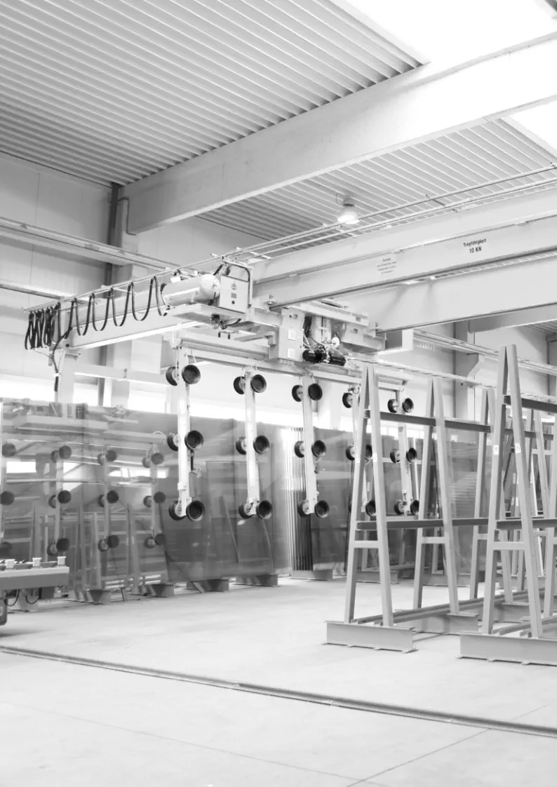
Mobile overhead crane with rotating suct
ion frame
for automatic pick-up of large-sized glass sheets
Fly
O
ver (
P
K
L / SB
H
)
p. 50
Revolutionary Loading System wit
h
Intelligent Glass Positioning
L
B
R
p. 52
Mobile slot rack system
R
P
S
p. 53
Compartmental storage f
or glass remnants
from optimized glass cutt
ing

Ma
c
hi
ne
ry f
o
r Loading,
Gl
ass Cutt
i
n
g & Logistics
Ta
b
l
e of Contents
06
07
Mobile Sorting
M
S
B
p. 58
Mobile sorting buffer for automatic and
manual loading of glass sheets
M
L
D
p. 60
Manual loading and unloading station
for mobile sorting buffers
M
S
B
-
T
p. 61
Automatic loading syst
em for mobile sorting buffers
A
L
D
p. 62
Automatic loading station for mobile sor
ting
buffers
onar
y S
or
ting
p. 64
Stationary Sorting
A
S
M
p. 66
Automatic sorting magazine
S
H
L
-
VH
p. 68
Automatic glass transpor
t shuttle with tilt function
S
H
L
p. 70
Glass Transport Shuttle
R
H
H
p. 72
Robot handling syst
em for tempering
bed loading and unloading
R
H
V
p. 74
Automatic vertical loading and unloading via robot
Se
rvi
ce
S
er
v
ices
p. 78
We offer you worldwide service and the
fastest poss
ible supply of spare parts.
P
r
ojec
t management
p. 80
Competence Ce
nte
r
G
L
A
S
T
EC
H
p. 82
Competence Center f
or research, production and
training in the field of flat
glass processing
Ma
c
hi
ne
ry f
o
r Loading,
Gl
ass Cutt
i
n
g & Logistics


L
IN
ES
We adapt the LiSEC lines to your production re
quirements. Combine innovative
systems from the glass processing, glass cutting, tempering and logistics areas
into a complete line system. O
ur employees are happy to advise you in order to
configure tailor-made line solutions with you. In order
to use the full efficiency
of your production, cross-line soware solutions a
re available.

Options & Software
Version with an additional infeed
section to increase output
Automatic turning of large glass sheets
Version with two cutting head
s
for automatic tool changes
Processing of 12.12.4.56 PVB mm
Recording of edge dele
tion contour
and possible automatic corre
c-
tion of the cut position
Four conve
yor belts for float glass
Automatic float glass b
reak-out
thanks to X sub-plate break-out
Six conveyor
belts for automatic
outfeed of cut LSG glass sh
eets
as the basis for a subseque
nt
VSL-A double bridge or do
wns-
tream sorting system or robot
P
rocessing of W cuts
Edge
deletion with grinding wheel
Automatic special shape cut

hand


oad


mon
prod


autofab


dynopt


assetcheck


ident


label

Highlights
Up to approx. 45 cut sheets of glass per
hour
with a VSL-A cutting bridge (X, Y, Z cuts)
Fully automatic cutting of laminated sheets of glass
Reduction of operator interventions
Cutting
LSG
quickly
and
flexibly
(output
versus comfort
mode)
Incr
ease in edge strength thanks to
clamping beam technology
Less wastage thanks to 20 mm trim cut
Automatic off-cut disposal up to 300 mm
Segmented infra
red film heating (SIR) for rapid
heating and re
duced energy consumption
Innovative operating concept with compre-
hensive machine intelligence
Permanent work surface monitor with laser
scanner for the high
est system safety


10
11


VSL-A laminated glass cutting system
with positioning station
LiSEC‘s VSL-A horizontal cutting system lays the groundwork for successful processing of laminated glass.
Since market introduction, a substantial increase in output has been achieved by th
e pate
nted SIR film heater
combined with significantly reduced glass waste, and less operator
interv
ention due to increased automation.
To provide solutions that best meet individual needs, LiSEC has d
eveloped a modular laminated glass cutting
system solution that can be
adapted step by step as r
equired and expand
ed with another VSL-A bridge.
The system has various operating modes between which you can select at any time: output or comfor
t mod
e. In
comfort mode, the sy
stem continuously produces fully cut glass lites sheets with almost no human intervention.
In output mode, additional production capacities can also be made availa
ble. Here the operator assists the syst
em
in separating remnants, which again makes for higher
output, a special advantage during production peaks.
High-performance system for cutting float and lamin
ated glass automatically
Technical data
VSL-A37/33
VSL-A47/33
VSL-A61/33
Min. glass thic
kness
2.2.0,38 PVB mm
Max. glass thickness (VSG)
10.10.4,56 PVB mm, optional 12.12.4,56 PVB mm
Glass thickness (Float)
2 - 19 mm
Min. processing length
200 mm
Min. processing width
150 mm
Min. size of sub-plate tur
ning
610
x 380 mm
Min. trim cut thic
kness (LSG) (VSG)
20 mm
Max. disposal of off-cuts
300
mm (automatic)
Max. cutting speed
140 m/min
Min. float glass sub-plat
e break-out
250 mm (op
tional)
Glass cutting tolerance
+/- 0.4 mm
Max. processing length
3,700 mm
4,700 mm
6,100 mm

Options
Tand em function on second VSL-A cutting bridge Processing of float glass and automatic break-out of sub-plates on the second VSL-A bridge Automatic conveyor belt removal of LSG broken glass pieces
12
13

VSL-A Double Brid
ge System Sol
utions
High-performance machine for cutting laminate
d safety g
lass automatically
This is based on an automatic glass storage facility in combination with a sy
stem for edge deletion or removal
of the LSG film overhang, and a VSL-A type of laminated glass cutting bridge
with conveyor belts. Then,
depending on the production quantity and variety
, users can choose betwe
en two system solutions.
Example: Customer “Type A” has a high number of variants in its product mix (many X, Y
and Z cuts). Here
, with an additional VSL-A unit on the first laminated glass cutting bridge,
it is possible to product up to about 75 panes an hour in fully automatic mode.
Optimum and dynamic utilisation of both VSL-A cutting bridges is assured by the int
elligent ‘Dynamic Load
Balancing’ (DLB) system. Moreover, this system solution features various operating modes between w
hich
the
operator can switch at any time: Output or comfort mode. When comfort mode is selected, the sy
stem
continuously produces fully cut glass lites sheets with almost no human intervention. In output mode, additional
production capacity can be made available. Here the operator assists t
he system, especially in separa
ting
r
emnants at the second cutting bridge, which again makes for higher output,
a special advantage during
production peaks.
Example: Customer ‘Type B’ produces a large numb
er of identical products and is involved in volume production,
(many X and Y cuts with identical dimensions). With a tandem version of the VSL-A system (cutting two glass
shee
ts
simultaneously), it is possible to calculate up to a quantity of about 140 sheets an h
our. In tandem mode, it is possible to cut
two glass sheets simultaneously on the second VSL-A in fully automatic mode. This system solution a
chieves the highest
possible output numbers and represents the fastest LSG cutting system on the market, especia
lly
for series formats.


Technical data
VSL-A37/33
V
SL-A47/33
VSL-A61/33
Min. glass thickne
ss (LSG)
2.2.0,38 PVB mm
Max. glass thickness (L
SG)
10.10.4,56 PVB mm, optional 12.12.4,56 PVB mm
Glass thickness (float)
2 - 19 mm
Min. processing length
200 mm
Min. processing width
150 mm
Min. size of sub-plat
e turning
610 x 380 mm
Min. float glass sub-plat
e break-out
250 mm (optional)
Glass cutting tol
erance
+/- 0.4 mm
Max. processing length
3,700 mm
4,700 m
m
6,100 m
m

Highlights
Dynamic Load Balancing (DLB) enables both bridges to
be utilised to an op
timum level
Up to about 75 cut sheets of glass per hour (X, Y
and Z cuts) with the VSL-A double bridge
Up to about 140 cut sheets of glass per hour (X, Y and Z
cuts) with the VSL-A double bridge with tandem function
Expansi
on option for the existing VSL-A system


Options
90° line variant depending on
the building situation
Y sub-plate tandem function is possible
automatische F
loat Scherbe
nabförderung
Automatic conveyor belt removal
of broken float glass pieces

Highlights
Fully-automatic float break-out system
Space-saving system conceptModulare
Modular expansion option
Smalle
r number of containers for broken glass pieces
14
15


Float G
lass Breakout Systems
Machines for Automatic C
utting and Breaking of Float Glass
The automatic float glass b
reakout systems consist of an automatic glass storage unit combined with a downs
tream
float glass cutting table for Low-
E edge deletion and for scoring the float glass sh
eets. Depending on the volume
of production and the variety of products, it is possible to sele
ct between three d
iffe
rent variants:
Example: Customer “Type A” would like to break X sub-plates and X edge sections automatically. With an automatic ARS
edge deletion station and a TBX break-out station the operator can be supporte
d to an optimum standa
rd. Output increases.
Example: Customer “Type B” would like to break X and Y sub-plates as well as X and Y edge sections automatically
. With
an ARS edge d
eletion station, a TBX break-out station, a TDV rotary table and
another TBR/TCY break-out station, it is
only necessary to break Z sections manually. This system is already highly automa
ted and achieves high
output leve
ls.
Example:
Customer
“Type
C”
w
ould
like
to
break
X,
Y
and
Z
sub-plates
a
s
well
as
X,
Y
and
Z
edge
sections
automatically.
With
an
ARS
edge
deletion
station,
a
TBX
break-out
station,
a
TDV
rotary
table,
a
TBR/TCY
break-out
station
and
an
SDV
sheet turning unit, virtually unmanned and continuous production of
fl
oat glass is possible at high lev
els of output.
With a well thought out system arrangement, the
numb
er of crates of broken glass pieces is reduced and
this has a positive
impact on system availability.
The optional automatic sheet disposal system maximises system availability.
Technical data
ARS / TCY
TBX / TBY (-XX/12)
TBX / TBY (-XX/19)
TBR
Maximum glass thic
kness
12 mm
12 mm
19 mm
19 mm
Automatic break-out
Side trims
Traverse breaks
Traverse breaks
Traverse breaks,
Side trims
Minimum size
350 x 350 mm
350 x 350 mm
350 x 350 mm
350 x 350 mm
Automatic disposal of broken glass
pieces
--
Automatic removal of broken
glass pieces
○
--
○
standard, ○ optiona
l, - not available


Ensure a smooth production with the LiSEC stand-alone machine
s. We
do not
only support you in the field of insulating glass production, with the LiSEC
insulating glass machines, but also with machines for glass cutting or glass
processing, sorting and logistics systems as well as tempering furnaces.
S
TAND-ALONE
MACHINES

18
19


DSC-A
GFB
ESL-RS
Sprintcut
Basecut
Max. glass thickness
2 - 19 mm
Cutting speed
160 m/min
120 m/m
in
120 m/min
220 m/mi
n
140 m
/min
Acceleration X/Y axis
6
m/s
2
4
m/s
2
X-axis
6
m/s
2
Y-axis
4
m/s
2
X-axis
6
m/s
2
Y-axis
10
m/s
2
4
m/s
2
Cut tolerance
+/- 0.2 mm
+/- 0.2 mm
+/- 0.15 mm
+/- 0.10 mm
+/- 0.2 mm
Cutting wheel changer
○○○○-
Edge deletion
○
*
○
*
**
○*
*
LOW-E edge deletion max. speed
160 m/min
80 m/m
in
80 m/min
80 m/mi
n
20 m
/min
TPF / EasyPro max.
60 m/min*
25 m/m
in*
25 m/min*
25 m/mi
n*
-
More powerful suction
○○○
-
Hepa filter suction
○○○-
Tilting version
DSC-A60/33T
-
-
-
Flat glass cutting over
view
Standard, ○ optional, - Not available,
*
2 passes,
**
1 pass (simultaneous cutting & grinding)

Options
Edge
deletion of Low-E glass (grinding
wheel widths of 20 to 26 mm)
Fully automatic t
ool-changer
for cutting wheels
Int
egrated device for cutting
off remnant formats (RP-I)
Multi-t
ouch version of the control unit
Tilting version of breaker
bars or belts

Highlights
P
recise glass cuts and high edge strength
with LiSEC direct cutting technology
Low
-E edge deletion speeds of up to 160 m/min
Aut
omatic suction device with Hepa filter unit
Edge
deletion of stepped sheets of glass, TPF & EasyPro glass
360° grinding in one cycle
Automatic pressure control of grinding
head and cutting h
ead
Display of cutting w
heel wear and critical cutting oil level

20
21

DSC-A
High-performance machine for cutting flat gla
ss automatica
lly
The new DSC-A from LiSEC is a horizontal cutting machine for the automatic cutting of float glass.
The machine combines massive processing flexibility with optimum precision, a reliable process
and optimum quality of glass cutting as well as the option of Low-E edge d
eletion.
Low-E edg
e deletion
The complexity of coating systems is rising in response to the increasing proportions of solar protection and thermal
protection coatings in the insulating glass sector. The DSC-A constitutes an optimum basis for the rapid and efficient
processing of single to triple layers of silver thermal protection or solar protection coatings as well as coating systems
that use protective films (TPF or EasyPro). The proportion of complex coatings is rising conti
nuously. With its
recently developed design of grinding head and bridge structure, the DSC-A is equipped to meet future cha
llenge
s.
F
loat glass cutting
The glass-cutting table features LiSEC direct cutting technology and a gantr
y driv
e on the X-axis, assuring high
precision of +/- 0.20 mm. Operation is sim
plified by automatic control of cutting pressure and grinding pressure.
Operator interventions are reduced because, depe
nding on the
coating and thickness of the glass, different grinding
and cutting pressure levels can be set automatically. Cutting oil and cutting whe
el monitors ana
lyse the consumption,
display this preventively and draw attention to the pending need for a change of cutting wheel. St
ock she
ets of glass
are sent in automatically on the
conveyor belt and fully automated a
lignment is car
ried out by glass positioning aids.
Machine construction
The basic variant consists of a horizontal cutting table, equipped with convey
or
belt, to combine this sy
stem with automatic loading systems.
The DSC-A T-variant has a tilt function to facilitate manual loading and unlo
ading of sheets of
glass. In addition, conveyor belts or breaker
bars can be add
ed for stand-alone opera
tion.


Perfect edge quality irr
espective of glass thickness
The use of this directly driven cutting technology in combination
with the highly
stable and precise cutting bridge means that t
he
cutting quality is always perfect, even with thick float glass.
Top quality with Low-E edge deletion regardless of coat
ing
With the aid of decades of experience
in the
area of edge deletion, the
system
can be used to process single to triple sil
ver as well as coatings with special
protection (Easypro or TPF) to an optimum standard and with
out any
residue.
Simple and user-friendly
The system has been developed to ensure that the oper
ator
is a
lways
optimally supported by the machine,
and such that operation is
largely possible without glass-specific know-how. This increases the
e
fficiency of the system and
ensures consistent glass cutting quality.
Technical data
DSC-A 37/33
DSC-A 60/33
DSC-A37/33-T
DSC-A60/33-T
Max. Glass thic
kness
2 - 19 mm
Maximum size
3,700 x 3,300 mm
6,000 x 3,300 mm
3,700 x 3,300 mm
6,000 x 3,300 mm
Cutting speed X/Y axis
160 m/min
Acceleration X/Y axis
6 m/s
2
Glass cutting tolerance
+/- 0.2 mm
Edge deletion
Optional
Low-E edge deletion max. speed
160 m/min
TPF / EasyPro max.
60 m/min*, 2 passes
Edge deletion
Grinding wheel


Options
Edge deletion of Low-E glass (grinding wheel widths of 20 to 26 mm) Version with augmented suction, specifically for TPF & EasyPro gla ss Fully automatic t ool-changer for cutting wheels Setting up a suction bridge as the basis for a VB line combination Automatic positioning and printing of glass labels
Highlights
Optimum cutting quality with minimal tolerances
Edge
deletion of Low-E glass
Gre
at reliability & durability of the system
Processing of the
raw glass sheet
without mandatory trim cuts


22
23


GFB
Technical data
GFB-37/26
GFB-37/33
GFB-61/33
GFB-61/36
GFB-75/33
GFB-90/
33
GFB-120/33
Glass thickness
2 - 19 mm
Maximum size
3,700 x
2,600 mm
3,700 x
3,300 mm
6,100 x
3,300 mm
6,100 x
3,600 mm
7,500 x
3,300 mm
9,000 x
3,300 mm
12,000 x
3,300 mm
Cutting speed
X/Y axis
120 m/min
Acceleration X/Y axis
4 m/s
2
X-axis, 6 m/s
2
Y-axis
Glass cutting tolerance
+/- 0.2 mm
Edge deletion
optional
Low-E edge deletion max. speed
80 m
/ min
TPF / EasyPro max.
25 m / min*, 2 passes
Edge deletion
Grinding wheel
The GFB cutting table was developed for processing coate
d and uncoated sheets of float and or
namental glass. This
system provides the lowest glass cutting tolerances with a high degree of dura
bility
and reliability at the same time.
With the GFB you are perfectly prepared to me
et all modern cutting requirements. The cutting table is
equipped with an infinitely adjustable air cushion section and a non-slip and we
ar-resistant conveyor
belt. Inbound transport and the alignment of unprocessed sheets of glass is perfor
me
d either manually
or automatically using the conveyor belt sy
stem. When processing coated sheets of glass, th
e coating is
removed by a
grinding wheel during the first pass. Then the cutting pr
ocess starts automatically.
The quantity of cutting oil supplied is centrally controlled by the
hollow sha of the cutting whee
l holder.
To obtain optimum cutting quality, the program controls the maximum speeds and acceleration rates to
suit the type of cut. Data transfer for straigh
t and special shape cutting is effected centrally by the network
or a USB interface. The GFB can be precisely matched to your needs by ad
ding furth
er optional functions.
Machine for Automatic Flat Glass C
utting
Optionen
Version with
augmented suction, speci-
fically for TPF & EasyPro gla
ss
Fully automatic t
ool-changer
for cutting wheels
Setting up a suction bridge as the
basis for a VB line combination
Dynamic scrape
r brush
for lucid cleaning
Integrate
d device for cutting
off remnant formats (RP-I)

Highlights
Simultaneous cutting and grinding of straight lines
Extremely fast throughput times with simple coatings
Optimum cutting quality with minimal tolerances
360° grinding in one cycle
Gre
at reliability & durability of the system
Processing of the
raw glass sheet
without mandatory trim cuts


24
25


Technical data
ESL-37/26RS
ESL-37/33RS
ESL-61/33RS
Glass thickness
2 - 19 mm
Maximum size
3,700 x 2,600 mm
3,700 x 3,300 mm
6,000 x 3,300 mm
Cutting speed
X/Y axis
120 m/min
Acceleration X/Y axis
4 m/s
2
X-axis, 6 m/s
2
Y-axis
Glass cutting tol
erance
+/- 0.15 mm
Edge deletion
optional
Low-E edge deletion max. speed
120 m / min
TPF / EasyPro max.
25 m / min*, 2 passes
Edge deletion
Grinding wheel
ESL-RS
High-performance machine for cutting flat gla
ss automatica
lly
Fully automatic cutting table for float and special glasses using cutting whee
l technology.
The table is equipped with an additional grinding unit which allows so coatings to be removed
. Straight edges can there
by
be simultaneously cut and ground in a single process, which guarantees low cycle times wh
ile
offering maximum quality.
Shorter
cycle
times
with
maximum
quality
are
thus
guaranteed.
Standard
and
digitalized
special
forms
can
be
cut
with
ease.
The CNC program adjusts the maximum axis speed and acceleration to the shape being cut. Cutting path optimisation
provides the optional possibility of minimising axial movement and ensuring the shortest cutting and grinding
times. The modular machine concept of LISEC offers almost unlimited possibilities for any future extension to suit
requirements: integration into a sorting system, combination with a laminated glass cutting ta
ble or as a direct
link to an automated glass loading system. Discover new possibilities – we will be pleased to advise you.

Options
Edge deletion of Low-E glass (grinding wheel widths of 20 to 26 mm) Version with augmented suction, specifically for TPF & EasyPro gla ss Fully automatic t ool-changer for cutting wheels Dynamic scrape r brush for lucid cleaning Integrate d device for cutting off remnant formats (RP-I)
Highlights
Extreme
ly fast throughput times with
uncoated shee
ts of flat glass
Optimum cutting quality with minimal tolerances
Aut
omatic cutting and grinding monitoring
Display of consumption of cutting wheel and cutting oil
Intuitive operation
High-precision
Processing of the
raw glass sheet
without mandatory trim cuts


26
27


SprintC
ut
The flat glass cutting machine of the SprintCut series combines state-of-the
-art drive techno-
logy with decades of LiSEC know
-how in the automatic processing of flat glass.
The linear drive technology
assures the highest cutting speed and outstanding dynamics. Maximum acceleration
is approx. 10 m/s² and maximum speed is approx. 200 m/min. With only a few moving parts, the SprintCut
convinces with maximum availability while retaining low cos
ts for maintenance work and spare par
ts.
The high-performance line also features an integrated mea
suring syst
em which delivers impressive precision
of +/- 0.10 mm. Automatic control of cutting pressure and the new grinding pr
essure control function make
operation even e
asier, especially for companies with a wide varie
ty of glass types and coatings. In addition,
automatically set pressures are repor
ted to the control system and the
refore dynamic countermeasures ca
n
be taken in case of cha
nges. Cutting oil and cutting wheel monitors show the consumption and preventively
indicate a change. Stock sh
eets of glass are sent in automatically on the conveyor b
elt and fully automated
alignment is carried out by glass positioning aids. Cutting without zero cut is a standard featur
e with us.
High-performance machine for cutting flat gla
ss automatica
lly
base CU
T
The compact base CUT glass cutting machine is ideally suited
for cutting straight lines and shapes out of flat glass. Its
design ensures maximum precision and minimum cutting tolerances, as well as a long service life of the machine. In
the machine‘s basic model, loading is carried out manually through ‚free fall‘. Aer loading,
th
e glass can be manually
positioned against the reference ma
rks. When the operator initiates cutting, the machine automatically det
ects the glass
sheet‘s position in X and Y direction. The stock plate is positioned manually. This assures precise cutting of sheets of
glass.
Machine for Automatic Float Glass C
utting
Technical data
SPRINTCUT-61/33
Glass thickness
2 - 19 mm
Maximum size
6,100 x 3,300 mm
Cutting speedX/Y axis
220 m/min
Acceleration X/Y axis
10 m/s
2
Glass cutting tol
erance
+/- 0.10 mm
Edge deletion
Optional
Low-E edge deletion max, speed
80 m/min
TPF / EasyPro max,
25 m/min*, 2 passes
Edge deletion
Grinding wheel
Technical data
BASE Cut-37/26 Tilt
Glass thickness
2 - 19 mm
Maximum size
3,700 x 2,600 mm
Cutting speed X/Y axis
140 m/min
Acceleration X/Y axis
4 m/s
2
Glass cutting tolerance
+/- 0.20 mm
Edge deletion
Standar
d
Low-E edge deletion max. speed
20 m/min
TPF / EasyPro
Not possible
Edge deletion
Grinding pin

28
29


Laminated glass cutting over
view
VSL-A
VB
Max. glass thicknesses
10,10,4,56 PVB mm,
optional 12,12,4,56 PVB mm
8,8,2,28 PVB mm,
optional 12,12,4,56 PVB mm
Max. cutting length
6,100 mm
6,000 mm
Automatic min. trim cuts (cutting, breaking-
out & separating; depending on thickness of
sheet of glass)
20 mm
150 mm
Trim cuts min. (only scoring)
20 mm
20 mm
Automatic feeding
Automatic sub-plate turning
-
Machine mode ‘Output mode’
-
Selected infrared heating (SIR heating)
○
Cutting wheel changes without interruptions
○
-
Edge deletion
○
-
Standard, ○ optional, - Not available
Options
Version with an additional infeed section to increase output Automatic turning of large glass sh eets Version with two cutting heads for automatic tool changes Processing of 12.12.4.56 PVB mm Recording of edge dele tion contour and possible automatic corre c- tion of the cut position Four conve yor belts for float glass Automatic float glass b reak-out thanks to X sub-plate break-out Six conveyor belts for automatic outfeed of cut LSG glass sh eets as the basis for a subseque nt VSL-A double bridge or do wns- tream sorting system or robot P rocessing of W cuts Edge deletion with grinding wheel Automatic special shape cut
hand


oad


mon
prod


autofab


dynopt


assetcheck


ident

label

Highlights
Up to appro
x. 45 cut sheets of glass per hour
with a VSL-A cutting bridge (X, Y, Z cuts)
Fully automatic cutting of laminated sh
eets of glass
R
eduction of operator interventions
Cutting LSG quickly and flexibly
Incr
ease in edge strength thanks to
clamping beam technology
Less wastage thanks to 20 mm trim cut
Aut
omatic off-cut disposal up to 300 mm
Segmented infra
red film heating (SIR) for rapid heating
and re
duced energy consumption
Innovative operating concept with comprehensive
machine intelligence
Permanent work surface monitor with laser scanner
for the high
est system safety
30
31


LiSEC‘s VSL-A horizontal cutting system lays the groundwork for successful processing of laminated glass.
Since market introduction, a substantial increase in output has been achieved by th
e pate
nted SIR film heater
combined with significantly reduced glass waste, and less operator
interv
ention due to increased automation.
To provide solutions that best meet individual needs, LiSEC has d
eveloped a modular laminated glass cutting
system solution that can be
adapted step by step as r
equired and expand
ed with another VSL-A bridge.
The system has various operating modes between which you can select at any time: output or comfor
t mod
e. In
comfort mode, the sy
stem continuously produces fully cut glass lites sheets with almost no human intervention.
In output mode, additional production capacities can also be made availa
ble. Here the operator assists the syst
em
in separating remnants, which again makes for higher
output, a special advantage during production peaks.
VSL-A laminated glass cutting system
with positioning station
System for the automatic cutting of lamin
ated safety glass
Technical data
VSL-A37/33
VSL-A47/33
VSL-A61/33
Min. glass thic
kness (LSG)
2.2.0,38 PVB mm
Max. glass thickness (L
SG)
10.10.4,56 PVB mm, optional 12.12.4,56 PVB mm
Glass thickness (Float)
2 - 19 mm
Min. processing length
200 mm
Min. processing width
150 mm
Min. size of sub-plate tur
ning
610 x 380 mm
Min. trim cut thic
kness (LSG)
20 mm
Max. disposal of off-cuts
300 mm (automatic)
Max. cutting speed
140 m/min
Min. float glass sub-plat
e break-out
250 mm (op
tional)
Glass cutting tolerance
+/- 0,4 mm
Max. processing length
3,700 mm
4,700 mm
6,100 mm

Options
Segmented infra red film heating (SIR) for rapid heating a nd reduced energy consumption Automatic special shape cut Processing of 10.10.4.56 PVB mm Processing of 12.12.4.56 PVB mm Automatic control of the cutting pressure Automatic float sub-plate break-out up to 12 mm or 19 mm Automatic control of the cutting pressure
Highlights
Up to appro
x. 30 cut sheets of glass per hour
with a GFB-VB cutting bridge (X, Y, Z cuts)
Fully automatic cutting of laminated sh
eets of glass
Innovative operating concept with compre-
hensive machine intelligence
La
ser-supported positioning for straight cuts
Combination with a
stop table (VB-AL-A) possible to
increase the capacity of an existing system (GFB-VB-BT
S)

32
33


VB laminated glass cutting system
LiSEC‘s VB horizontal cutting system in combination with a float cutting table (GFB/ESL) or an
end-stop bridge (AL-A) lays the gr
oundwork for successful processing of laminate
d glass.
The vacuum suction cups that operate from below throughout the entire cutting process (scoring, bre
aking
out and film separating processes) constitute a substantial difference to the VSL-A system.
To avoid any additional stress enter
ing the glass, the suction cups can be moved.
Further to this, the r
aw glass sheet is positioned on the cutting table by a suction cup bridge on the cutting table a
nd is
cut in the VB. The remaining Y and Z cuts are performed once th
e glass has been turne
d manually and moved to its end-
stops.
The SIR film heating system can be
used to achieve a substantial improvement in output with the patented
SIR film heating. As standard, the system has a la
ser positioning aid for the cutting of special shapes.
System for the semi-automatic cutting
of
laminated safety glass
Technical data
VB-33
VB-37
VB-45
VB-60
Min. glass thic
kness (L
SG)
2.2.0,38 PVB mm
Max. glass thickness (L
SG)
8.8.2,28 PVB mm,
Glass thickness (float)
2 - 19 mm (optional)
Min. processing length
200 mm
Min. processing width
150 mm
Min. trim cut thic
kness (LSG)
150 mm (automatic)
Min. trim cut thic
kness (LSG)
20 mm (only scratch)
Max. cutting speed
140 m/min
Min. float glass sub-plat
e break-out
250 mm
(optional)
Glass cutting tolerance
+/- 0.4 mm
Max. processing length
3,300 mm
3,700 mm
4,500 mm
6,000 m
m

34
35


ARS / TCY
TBX / TBY (-XX/12)
TBX / TBY (-XX/19)
TBR
Max. glass thickness
12 mm
12 mm
19 m
m
19 mm
Automatic break-out
Trim cutting
Sub-plate breaks
Sub-plate bre
aks
Trim cut sub-plate
bre
aks
Minimum size
350 x 350 mm
350 x 350 mm
350 x 350 m
m
350 x 350 mm
Automatic disposal of broken glass pieces
--
Automatic removal of broken glass pieces
○
--
○
standa
rd, ○ optional, - not available
Using a break-out de
vice to remove the front and re
ar trim cut and break-out devices with 3-point technology for
X, Y and Z break-out can facilitate any desired automation variant. R
otating devices for straight brea
k-out lines
for glass pieces or 90° discharge stations in conjunction with automatic edge breaking device
s are available.
Break-out systems overview


36
37


ARS / TCY
ARS breaks and remov
es front and rear trim cuts of alread
y cut glass sheets across the
entire width of the sub-plates. The TCY removes the top and bottom Y trim cuts. Th
e
intelligent breaking device used ensures that trim cuts are neatly broken a
pa
rt.
Pieces of broken glass are disposed of automatically into a container for broken glass situate
d
below t
he machine.Even thin glass sheets can be easily proce
ssed and transported. Extendible
support rollers prevent any of th
e cuts being broken apart unintentionally.
Automatic break-out device for trim cuts
TB
X /TBY
Once the front and r
ear trim cuts have been removed
, the glass sheet is transported
to
the TBX on a belt transport unit. The TBX breaks out the existing X cuts int
o individual
sub-plates. The TBY breaks out the existing Y cuts into individual sheets of glass.
A pneumatic counter piece applies the counter pressure required to ensur
e neatly broken glass panes.
Automatic break-out device for sub
-plate breaks
Technical data
ARS / TCY -26
ARS /
TCY -33
Glass thickness
2 - 12 mm
Max. sub-plate width
2,600 mm
3,300 mm
Front trim cut
15 - 60 mm
Rear trim cut
15 - 250 mm
Technical data
TBX / TBY-26/12
TBX / TBY-33/12
TBX / TBY-33/19
Glass thickness
2 - 12 mm
2 - 12 mm
2 - 19 mm
Minimum size
350 x 350 mm
Max. sub-plate width
2,600 mm
3,300 mm
3,300 mm


38
39


TBR
TBR can break apart both trim cuts and Y-cuts. The sub-plates previously turned in the
TDV ar
e broken
out. In addition here, th
e front and, if required, the
rear trim cuts are removed. Here
too, pieces of broken
glass are also disposed of automatica
lly into a container for broken glass situated below the machine.
Automatic break-out device for trim cuts and sub-
plate breaks
TDV
The transport section of this space-saving machine is equipped with a roller drive and an inte
grated liing
and turning plate. This lis the glass sheet off, turns it 90° and then lowers it again. Following this, the
sub-plates are transported to the TBR or TCY / TBY sub-plate brea
k-out sys
tem to break out the Y-cuts.
Optionally, two nar
row sub-plates can be simultaneously tur
ned and transferr
ed to the downstre
am
breaker bar via split drives. This optional equipment allows an enormous increase in capa
city
.
Horizontal sub-pla
te rotating device 90°
Technical data
TDV-33
Glass thickness
2 - 19 mm
Minimum size
350 x 350 mm
Max. sub-plate length
3,300 mm
Max. sub-plate width
3,300 mm
Technical data
TBR-33
Sub-plate break glass thickness
2 - 19 mm
Trim cut glass thic
kness
2 - 12 mm
Minimum size
350 x 350 mm
Max. sub-plate width
3,300 mm
Front trim cut
15 - 60 mm
Rear trim cut
15 - 250 mm

40
41


Glass loading is the first step for successful glass processing. It must be designed in accordance
with the
requirements of th
e downstream systems and adjusted to th
e requirements of the product mix.
Our loading sys
tems can meet all customer requirements from high throughput and
high variability to easily supplying s
tandalone cutting systems.
G
lass loading overview
ATH
SIDE LOADER
(SLR)
RACK
SHUTTLE
SYSTEM
(RSS)
PKL / SBL
FlyOver
(PKL / SBH)
Glass thickness up to 19 mm
25 mm
25 mm
25 mm
25 mm
25 mm
Minimum sheet height
1,600 mm
1,800 mm
2,400 mm
1,600 mm
3,210 mm
Crane system---
Remnant plat
e store (RPS)
-
-
○
○
○
Automatic cardb
oard strip
remova
l
-
○
-
○
○
Automatic cover sheet
rea
rrangement
-
○○○○
Uninterrupte
d reload
-
-
*
*
standard, ○ optional, - not availab
le, * limite
d availability

42
43


1


Co
m
parison Stora
ge Systems
Available space: ~770m²
Example floor plans
Standard
crane storage
system (PKL /
SBL / LBK)
Compact
crane storage
system (PKL /
SBL / LBR)
Side Loader
(SLR / LBR)
Rac
k
Shuttle
System
(RSS / RSL)
Hybrid storage
system (RSS /
SLR or RSS / PKL
/SBL)
Number of storage positions
58
129
42
87
100
Storage capacity max.
852 t1,580 t
575 t1,044 t1,200 t
Fast access to the entire storage/warehouse
-
--
Fast repeated access to 2 - 3 types of glass
-
-
-
Residual sheet buffer
Shelving of residual sh
eet into the ware-
house
- ***
- ***
-
~
Max. number of cutting lines *
2
- 32 - 3
2
- 3, Scalable
with extr
a shuttle
2
- 3, Scalable with
extra shuttle
2
- 3
Uninterrupted reloading
**
**
-
Automatic inloader takeoff
- ***
--
-
* depending on the mix float/laminating and/or cycle time requir
ements
** possible to a limited extent.; defined loading and safety area according to the
cust
ome
r’s requirement
*** F
lyOver possible
Standard Crane Storage Syst
em (PKL / SBL / LBK)
Crane storage
system with standard stora
ge racks. Possible design as gantry, semi-gantr
y or bridge crane
.
Compact Crane Storage Syst
em (PKL / SBL / LBR)
Crane storage
system with compact shelf storage location. Possible d
esign as gantry, semi-gantry or bridge cr
ane.
Side Loader (SLR / LBR)
Ground-based side loader which takes out individual pane
s/sheets from th
e LBR.
Rack Shuttle System (RSS / RSL)
Ground-based package st
orage system which places entire r
acks including glass package in front of the used ATH-Ms.
Hybrid Storage System (RSS / SLR or RS
S / PKL /SBL)
Floor-based package rack storage location that provides complete ra
cks includ
ing
the glass package for the side
loader or gantry cra
ne located behind.

4

5

3

2

1
standa
rd, - not available

4

3

2

5


Options
Fast version with dual hydraulic system Double-Sided Movable design

44
45


Highlights
Fully automatic loading of cutting lines Loading from one side Handling of large and split stock sizes
Technical data
ATH-37/26 (D)
ATH-37/33 (D)
ATH-60/30 (D)
Glass thickness
2 - 19 mm
Minimum size
1,600 x 1.600 mm
1,600 x 1.600 mm
2,800 x 1,600 mm
Maximum size
3,700 x 2,600 mm
3,700 x 3,300 mm
6,000 x 3,300 mm
Travel path (glass rack sections)
1 - 81 - 81 - 8
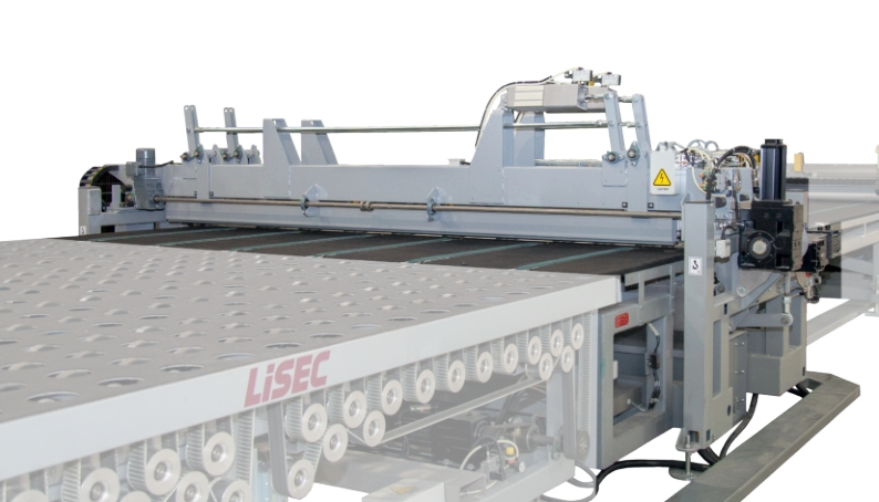
ATH
Glass sheets are automatically unloaded from storage racks positioned to one side of the mach
ine
, and tilted to the
horizontal position for the cutting process. Both the tilt mechanism and the frame with vacuum suction cups are
operated with
an oil hydraulic system. The loading machine is also availab
le in a mobile version with electronically
controlled drive system, which is capable of unloading glass she
ets from up to five
different sections.
Movable or Stationary Sing
le- / Double-Sided Glass Loading Mac
hine

Options & Software
Connection to remnant
plate storage system
Glass thickness 2 - 25 mm

prod


autofab

Highlights
Uninterrupted reloading of the glass storage
Saving of space due to the compact construction
Can be configured customer-specifically
for a flexible production


Options & Software
Double-sided design
Connection to remnant
plate storage system
Glass thickness 2 - 25 mm
Automatic cardboard strip removal
prod


autofab
46
47

Highlights
Saving of space due to the compact construction Can be configured customer-specifically for a flexible production Variably extendable


Technical Data
SLR-37/26
SL
R-52/33
SL
R-60/33
Glass thickness
2 - 19 mm
Minimum size
3,700 x 2,600 mm
5,200 x 3,210 mm
6,000 x 3,210 mm
Maximum size
3,700 x 2,600 mm
5,200 x 3,210 mm
6,000 x 3,210 mm
Side L
oader (SLR)
Fully automatic, mobile Glass Loading Station including linear br
ackets
Technical Data
RSS-37/26
RSS-60/33
Glass thickness
2 - 19 mm
Minimum size
3,700 x 2,600 mm
6,000 x 3,210 mm
Maximum size
3,700 x 2,600 mm
6,000 x 3,210 mm
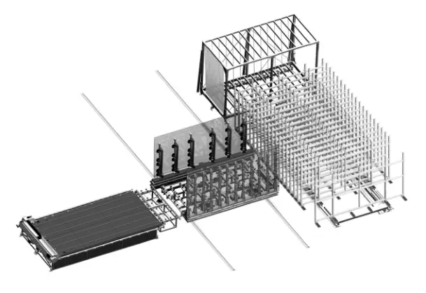
Rack Shuttle System (RS
S)
System for the taking out of large-format glass packages from automatically movable glass pac
ka
ge high-bay racking
systems. The transport shuttle automatically transports the r
equested glass package from the warehouse
to th
e cutting
plant. A separate oake station (ATH) feeds respectively loads the cutting (to size). A specifically arranged reloa
ding
station ensures an uninterrupted reloading of the glass storage. Thus, maximum output is achieved wit
h minimum idle
times. This plant is designed for glass-processing companies with only few types of gla
ss but a high throughput.
Glass Package High-Bay Racking with Shuttle Transport
System for the taking out/off of large
format glass sheets from automatically movable sh
elf rack
storage systems (LBR). The subsequent tilting of th
e sheets for the transport to the cutting tab
le
is also performed fully automatically. A gr
ound-based war
ehouse/storage system with side
loader dispenses with the commonly used crane gird
er and may there
fore be used in any type of
hall.

Options & Software
180 degrees rotatable design of suction frame Glass thickness up to 25 mm Glass loading from inside-loader Connection to remnant plate storage system
prod


autofab


assetcheck


ident
48
49

Highlights
Supports up to 60 loading positions Double-sided tilting and rotating suction frames are available Optimized travel routines for the shortest possible cycle times Available in half and full gantry versions


Technical Data
SBL-37/26KR
SBL
-37/33KR
SBL-60/30KR
Glass thickness
2 - 19 mm, optional 2 - 25 mm
Minimum size
1,600 x 1,800 mm
2,800 x 2,400 mm
2,800 x 2,400 mm
Maximum size
3,700 x 2,600 mm
3,700 x 3,300 mm
6,000 x 3,300 mm
PKL / SBL
Gantry system with electronically controlled floor drive
units;
runs on flat guide rails or directly on
concrete floors. The automatic driv
e synchronization is controlled by optical sensors and
ensures exact
positioning of the loading system relative to the receiving station. The
robust bridge drive sy
stem ensures
exact positioning of the double suction frame and is available in rotating or tilting ver
sions.
Process-controlled operation from pickup of large-sized
sheets through to transfer to the turning
table. A special high-speed version is also available with multiple drives and pre
cision guides for
the floor and gantry movement along with optimize
d handling and travel proced
ures.
Mobile overhead cr
ane with rotating suction frame
for automatic pick-up of large-sized glass sheets

Options & Softwar
e
Version for split stock sizes
Combined
with
RPI
option,
cutting system
at the fee
d side of the cutting table, for
maximum gain in time. Any remnant
sheets produced during cutting a
re fed
out again immediately, tilted up with
the SBH and returne
d to the glass store
Automatic cardb
oard strip removal
Connection to remnant
plate storage sy
stem
prod


autofab


assetcheck


ident
Highlights
Moves diagonally and is therefore the fastest system available Renders remnant plate storage systems obsolete As many positions for remnant plates available as there are storage racks Intelligent optimisation system to avoid remnant plates to the greatest possible extent

50
51


Technical Data
FlyOver (PKL / SBH)
Glass thickness
2 - 19 mm, optional 2 - 25 mm
Minimum size
1,500 x 3,300 mm
Maximum size
6,000 x 3,300 mm
FlyOver (PKL / SBH)
The newly developed FlyO
ver overhead loa
ding system is sma
rter and faster tha
n loading systems were ever
before. It is provided with a redesigned suction cup frame and can move diagonally ab
ove
the storage racks
when empty. Once
a coated sheet has bee
n unloaded, the suction cup bridge can immediately move towa
rds
the next storage rack and the loader can be tilted down instantly. This process allows minimum cycle times,
as the suction cup bridge does not h
ave to move out from in between the r
acks aer each cycle.
Intelligent Optimisation Syste
ms
LiSEC optimisation systems avoid remnant plates whenever possible. If they cannot be avoided, though, th
e intelligent
system puts the remnant plates first for coming orders. Any collisions in the process are therefore eliminated. If
necessa
ry
, for example when storing glass that has just been delivered, remnant pla
tes ca
n be repositioned automatically.
This advanced sy
stem is based on long-term experience with manual syst
ems and the proven ATF loading system by
LiSEC. It is the best optimisation system currently available for your glass s
torage and overh
ead loading system.
Revolutionary Loading System with Inte
lligent Glass Positioning

Options & Software
Glass thicknesses up to 25 mm
prod


dynopt

Highlights
One remnant plate storage system for multiple cutting systems Several remnant plates per rack possible Compact, space-saving design Vertical construction enables easy cleaning Can be adapted to the relevant production requirements


Options & Software
Double load Manual design
prod
52
53

Highlights
Efficient space use thanks to mobile slot racks
Many storage locations in a small space


Technical Data
LBR-37/26
L
BR-52/33
LBR-60/33
Glass thickness
2 - 25 mm
Minimum size
1,880 x 1,600 mm
2,800 x 2,400 mm
2,800 x 2,400 mm
Maximum size
3,700 x 2,600 mm
5,200 x 3,300 mm
6,000 x 3,300 mm
Number of slots
10 - 50
Storage area
140 - 600 mm
LBR
Automatic mobile slot rack system for efficient use of the existing storage space. Thanks to th
e mobile
compartments, the minimum clearance between the racks can be kept sma
ller. The required ra
ck is
extended in advance and the jumbo sheets re
move
d automatically by our loading system.
Mobile slot rac
k system
Technical Data
RPS-45/33-30
RPS-60/33-20
RPS-60/33-30
RPS-60/33-35
Glass thickness
2 - 19 mm
Minimum size
1,500 x 1,600 mm
Maximum size
4,500 x 3,300 mm
6,000 x 3,300 mm
6,000 x 3,300 mm
6,000 x 3,300 mm
Compartments
30
20
30
35
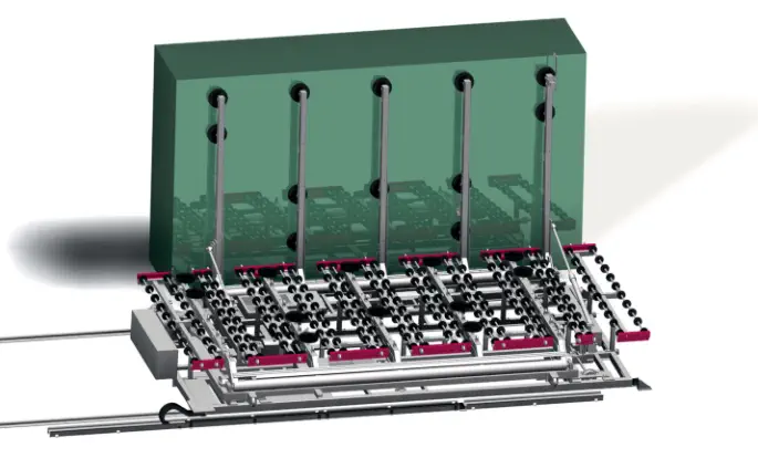
RPS
Our compartment modules for vertical storage of glass remnants from optimized cutting procedures
are to be positioned as close as possible to the cutting table’s loading station. Rest glass from the
cutting table is transported back to the tiltable loading and unloading table as deter
mined
by
the production control soware before being slid int
o their vertical storage positions.
The
linear
transportation
of
the
gla
ss
sheets
to
the
individual
compartment
slots
is
carried
out
by
a
traveling
and
self-positioning
roller
carrier.
As
the
storage
module
is
laid
out
for
extra-large
sizes,
this
system
also
functions
as
a bu
ff
er storage for uncut sheets in the event of temporary interruptions to the loading of glass st
orage racks.
Compartmental storage for glass remnants from optimized glass cutting

54
55


Available
, - Not Available
LiSEC logistics systems are adapted to the customer’s individual requirements from both a
technical and automation point of view and can grow with the customer (growing sor
ting
system) - from a simple manual system to a complex, fully automatic solution.
A fully automatic logistics solution has a positive effect on the output quality, for example
because the number of glass sheet scratches is reduce
d. An optimised sorting system enable
s
exact information about the current location of the sheet to be
pr
ovided.
Lo
g
istics systems overview
Mobile sorting
Stationary sorting
MSB
MSB / MLD
MSB / ALD
MSB / MSB-T
ASM
SHL
SHL-VH
Mobile sorting
-
Stationary sorting----
Automatic
-
-
Manual
----
-
Vertical
Horizontal------
Glass thickness
2.3 - 17 mm
2.3 - 17 mm
2.3 - 17 m
m
2.3 - 17 mm
2.3 - 25 mm
2,3 - 19 mm,
optional
2,3 - 25 mm
2,3 - 19 mm,
optional
2,3 - 25 mm
Special shapes a
ccording to
the LiSEC catalogue
Coated glass sh
eets lites
Angling
3°
3° / 3 - 6°
3°
3°
2°
2 - 8°
2 - 90°
Chaotic loading
-
--
Sequential loading
-
--
Single load
Double load
-
-
Multiple load---
-


Patented rotatable frames
Mobile Sor
ting
56
57


Options
44 slots (glass thickness: 2.3 - 12 mm)
58
59

Highlights
Logistics solution patented by LiSEC Flexible and ergonomic transport No contact with the glass plates Autofab / AFOverview soware solutions Can be applied individually throughout the entire production process

Technical Data
MSB
Glass thickness
2.3 - 17 mm
Number of slots
34 (2.3 - 17 mm) / optional 44 (2.3 - 12 mm
)
Minimum size
350 x 180 mm
Maximum size
3,000 x 2,200 mm
Maximum load
2,000 kg
Angle of inclination
3°
MSB
The mobile sorting buffer (MSB) is an integral part of in-house logistics solutions and can be
used in a highly flexible manner. Depending on the selected design,
th
e buffer is in a class of its
own whe
n it comes to loading and
unloading glass sheets manually or automatically.
In automatic operation, the glass she
ets are fed in on roller ca
rriers arranged
below the MSB and then
put on the glass support bars integrated in the mobile sorting buffer as soon as the roller car
rie
r lowers.
In this way, temporary storage even of very large sheets is possible without oper
ator inte
rvention.
There is also the option of replacing the glass support bars with glass transport rollers, which enables manual load
ing a
nd
unloading.
Mobile sorting buffer for automatic and manua
l loading of glass sheets
Manual loading
The mobile sorting buffer can also be loaded in a purely manual fashion. In this case we recommend using an “infe
ed
roller”.
MLD - Manual loading station
The manual LiSEC loading and unloading station (MLD) can be integra
ted directly within a production line or used as a
stand-alone ma
chine.
ALD / TSC - Automatic loading stat
ion with sequential automatic loading
Using the automatic loading and unloa
ding station (ALD), the glass sheets ar
e transferred sequentially
by way of a
roller carrier situated b
eneath the MSB.
MSB - Chaotic loading
Single glass loading and a chaotic system are both possible with the MSB-T. Temporary storage even of ve
ry large
sheets is possible without operator intervention.sequentially by way of a roller carrier situat
ed beneath the MSB.

3

4

2

1
Can be applied individually throughout t
he entire production process
Depending on the selected design mode, the sorting buffer MSB can be load
ed and unloaded automatically or manually
.
Th
e following variants are availab
le: Automatic loading station (ALD), automatic loading with shuttle (MSB-T), manual
loading using a station (MLD) and manual loading by h
and.
Logistics solution pat
ented by LiSEC
The patented rotatable frames of the MSB ensure that th
e loading process can be performed safely from either
sid
e.
Glass coatings remain untouched during tr
ansport
Highly sensitive system for coated
sheets: Thanks to the 3° angle nothing comes into
contact with the glass she
ets and the coatings remain undamaged.
Loading and unloading possibilities wit
h the MSB


Softwar
e

Highlights
Fully automatic loa
ding and unloading
in conjunction with the shuttle
The
glass quality is retained thanks to
the fully automatic process
Re-sorting is possible in order to be able to fill the
insulating glass line without interruptions
Optimised cycle time


autofab


Options
Additional MSB harp rack position
Highlights
Chaotic loading with upstream machinery (RKT, RTV) or manual positioning Integrated inclined change-over function from 3° to 6° Expandable to up to six MSB positions Easy, intuitive operation
60
61


MLD
Manual loading and un
loading station for mobile sorting buffers
Technical Data
MLD
Glass thickness
2.3 - 17 mm
Minimum size
350 x 180 mm
Maximum size
3,000 x 2,200 mm
Transport height
520 mm
Maximum load
150 kg
Angle of inclination
3 - 6°
The LiSEC MLD is a manual loading and unloading station for mobile sorting buffers (MSB-A) th
at
may be integrated
directly within a production line or used as a stand-
alone machine.
The loading/unloading station comprises a moveable roller wall that is guided on a rail on one
sid
e. If
this roller wall is placed in front of a sorting buffer slot ma
nually, glass sheets may be removed
from
the buffer or inserted into the buffer manually. If the glass sh
eets are placed onto the load
ing station
from the sorting buffer then they can be transferred to an insulating gla
ss line
or onto a stationary
roller wall manually. They may then be used for other processing steps from the stationary r
oller wall.
This system is particularly well-suited for quick a
nd elective sorting of glass sheets.
MSB-T
During the loading process, the glass sheets are fed in automa
tica
lly by way of a roller ca
rrier situated unde
rneath.
As soon as the roller
carrier is lowered, the
glass sheet is placed on the integrated glass tr
ansport rollers. When it
comes to the automatic unloading process, this sequence is per
formed
in r
everse -> th
e roller carrier lis the glass
she
ets off the glass transport rolle
rs and transfers them out of the MSB. Single glass loading and a
chaotic system are
both possible with the MSB-T. Temporary storage even of ver
y large sheets is possible without operator intervention.
Automatic loading system for mobile sorting buffers
Technical Data
MSB-T
Glass thickness
2.3 - 17 mm
Minimum size
350 x 180 mm
Maximum size
3,000 x 2,200 mm
Transport height
520 mm


autofab
Softwar
e

Highlights
Fully automatic mobile sorting buffer (MSB) loading and unloading The glass quality is retained thanks to the fully automatic process Optimised cycle time
62
63


ALD
Using the automatic loading and unloading station (ALD), the glass sheets are transferred se
que
ntia
lly by way
of a roller carrie
r situated beneath the MSB. A back wall supports the glass sh
eet and double-loading is possible.
Automatic loading station for mobile sorting buffers
Technical Data
ALD
Glass thickness
2.3 - 17 mm
Minimum size
350 x 180 mm
Maximum size
3,000 x 2,200 mm
Transport height
520 mm
Maximum load
2,000 kg


Stationar
y Sorting

Modular composition of the sorting magazines
according to customer requirements
64
65


autofab
Softwar
e

Highlights
Fully automatic sorting magazine Modular composition of the sorting magazine according to customer requirements Operating/feeding production lines Direct transfer of a glass sheet from a cutting system (only in conjunction with our LiSEC shuttle sorting system - SHL).
66
67
ASM
Glass sheets can be pre-sorted and stored inter
mediately in the automatic sorting magazine. Loading and
unloading is performed via a separately controlle
d transport beam in conjunction with a glass transport shuttle.
The transport roller bar moves on guide rails located below the magazine unit,
positions itself exactly und
er
the active storage slot, tilts th
e drive rollers towar
ds the transport level and starts to transport the
sheet.
Sorting in the storage magazine is performed by production process soware
(optionally available from LiSEC) by optimising the following criteria:
Number of free buffer slots
Shortest transport paths
Need-based r
equest from production line
Automatic sorting magazine


Technical Data
ASM
Glass thickness
2.3 - 25 mm
Glass height
2 m / 2.7 m / 3.3 m
Glass length
4,500 / 5,000 / 6,000 mm
Minimum size
350 x 180 mm
Maximum size
6,000 x 3,300 mm
Transport height
520 mm
Maximum load
156 kg/lm
Angle of inclination
2°

Softwar
e


autofab

Highlights
This flexible tilting shuttle enables customer require-
ments to be met despite limited available space.
One tilting table per line can be saved with the tilting sh
uttle.
Progressively adjustable horizontal and
vertical glass tr
ansport height
Glass transport function with sim
ultaneous possi-
bility for turning over or tilting up glass sheets
Optimised cycle time – glass sheets are transported
to the end
of the shuttle transport carriage w
hile
moving and are adjuste
d to the required angle
of the downstream st
ation (2 – 90 degrees)
Maintenance-friendly – automatic lubrica-
tion system, low-maintenance components,
easily replace
able wearing parts
Standardised LiSEC rail system – can
be expanded
without difficulty
68
69


SHL-VH
The tilting shuttle can transport glass she
ets both horizontally and vertically betwe
en processing stations.
The tiltable glass shuttle can cover the standard tilts of 2-6° and the full range up to 90° (hor
izontal). It use
s the
same rail system as the standard shuttle and can ther
efore accelerate
highly
dynamically at a speed of up to 300 m/
min and 3 m/s². The LiSEC tilting shuttle combines the functions of a tilting table with those of a shuttle. Horizontal
and vertical glass transport lines each wit
h different transport heights and tilts can be operated
with one shuttle.
Automatic glass transport shuttle with tilt function
Technical Data
SHL-VH
Glass height
2.5 m / 2.7 m / 3.3
Glass thickness
2.3 - 19 mm
Minimum size
350 x 180 mm
Maximum size
4,500 x 3,300 mm
Transport height vertical
520 mm
Transport height horizontal
865 – 970 mm
Travel speed
up to 300 m/min
Shuttle acceleration
up to 3 m/s²
Vertical transport speed
3 - 36 m/min
Maximum load
150 kg/lm
Angle of inclination
2 - 90°

Softwar
e


Highlights
Best suitable for coated glass
Due to the d
eclanation the coated surface will
never be touched during movement
Shortest cycle time
Thanks to a bigger decla
nation glass can be trans-
ported within the shuttle while moving the sh
uttle
Increased Life Tim
e
A central lubrication sys
tem avoids downtime
and guarantees long lasting components


autofab
70
71


SHL
The glass transport shuttle type SHL will be
used for loading and unloading of IG-lines, glass
processing machinery or buffer systems like the Lise
c ASM. The
glass is transported on to the
shuttle vertical and automatica
lly determining the number of lites loaded onto the sh
uttle.
The combination of high-performance roller guides and helically toothed rac
ks minimizes driving
resistance and maximizes stability,
allowing an acceleration of up to 3 m/s² and transport speeds of
up to 5 m/s (300 m/min). Additionally, the back wall of the transport is strongly incline
d. As a result,
the transport of the she
ets in the shuttle can proceed contact-fr
ee, further improving the cycle time.
Glass Transport Shuttle
Technical Data
SHL
Glass height
2 m / 2,5 m / 2,7 m / 3 m / 3,3 m
Glass thickness
2,3 - 19 mm
Minimum size
350 x 180 mm
Maximum size
6,000 x 3,300 mm
Transport height
520 mm
Transport speed
up to 300 m/min
Acceleration Shuttle
up to 3 m/s²
Transport speed vertical
3 - 36 m/min
Maximum load
150 kg/lm
Angle of inclination
2 - 8°

Softwar
e


autofab
Highlights
Maxim
um flexibility
Glass sheets can be freely positioned, depending
on the requirements of th
e subsequent
tempering bed.
Parameterisable tempering bed r
estrictions
Reduced space requir
ements
Turing sh
eets directly on the robot
Consistent q
uality
Optimum tempering bed utilisation
Staff savings
-
72
73
RHH
The stationary sorting runs automatically using the robot handling syste
m f
or tempering bed loading and unloading.
G
PS
.
autofab calculates the necessary glass shee
ts for the tempering oven batch. The
se are then transported in th
e specifie
d
sequence from the sorting onto the horizontal transport section (BTA) in front of the temper
ing oven. The
sheet stops at the
end of the BT
A: Size, weight, number of suction cups, start a
nd end coordinates, and the placement mode
are transmitted
to the robot, and the required suction cups are activated. These
can be activated individually to fa
cilitate
adjustment to the
required contour and processing (cut-outs, drilling, etc.). The rob
ot then picks up the
glass sheet for „Pick and Place
“ or for
„Drag and Drop“ mode. In case of the “Pick and Place“ function, small sheets are lied into the spe
cified
position. On the
other hand, large sheets are pushed into the specified
position via the air cushion using the “Drag and
Drop“ function. The
glass sheet is rotated or offset laterally if necessary, and subsequently move
d into the position spe
cified
by t
he
G
PS
.
autofab.
Robot handling system for tempering bed loading and unloading
Technical Data
RHH „Pic
k and Place“
RHH „Drag and Drop“
Minimum size
350 x 180 x 2 mm
Maximum size
2,800 x 1,600 x 10 mm
6,000 x 3,300 x 19 mm
Maximum load
125 kg


autofab
Software
74
75

Highlights
Guarantee of continuous production Increased safety for employees Consistent product quality High flexibility in adapting to the glass blocks / transport containers Reduction of personnel costs Reduced space requirements


RHV
As a result, the insulating glass line can be loaded fully automatically with individ
ual sheets of glass or
unloaded with insulating glass units, ensuring a stable and continuous process. The fixed
support finger
s
and the extendable suction clamps facilitate
low-impact transport of elements with thermoplastic spacers.
The linear arrangement of the suction clamps facilita
tes the re-turning of the units if necessary.
Automatic vertical loading and unloading
via robot
Technical data
RHV
Min. glass size:
350 x 180 x 3 mm
Max. glass size:
4,000 x 3,300 x 60 mm
Maximum glass load:
RHV-A50 = 50 kg
RHV-A100 = 100 kg
RHV-A200 = 200 kg
RHV-A300 = 300 kg
RHV-A400 = 400 kg
RHV-A480 = 480 kg


SER
V
ICE
Machines and systems for flat glass pr
ocessing are in use for many
years, sometimes even for deca
des. Ongoing maintenance and
optimisation are essentia
l to keep performance, e
fficiency and
availability at a consistently high leve
l and to ensure high-quality glass
products.


78
79

Service P
roducts
Online Support Ho tline Service / Maintenance Training LONGLiFE Spare parts Installation Repairs
Services
From machine installations to modernization of existing systems, we offer a wide range
of services,
and stay on your side as a compe
tent and reliable partner th
roughout the entire life cycle of your
systems. Whether
you need a customized training program, detailed machine inspections, online
support, spare parts or upgrades – the LiSEC service
team will take care of it for you.
We offer you worldwide service and the
fastest possible supply of spare parts.
Facts & figure
s:
More 140 service engineers worldwide Global network with local partners all over the world Spare part deliveries worldwide within shortest time Super-fast problem solving via remote service Compentent technical consultingOnline Support
Telephone support with direct data connection to your LiSEC machinery for the immediate and targeted diagnosis and correction of faults and errors.Machinery
Sunday 10:00 p.m. – Friday 09:00 p.m. (CET) Phone: +43-7477 405-5701 E-Mail: tbe.service@lisec.com Emergency contact for urgent issues outside our working h ours: Saturday 6:00 a.m. – 10:00 p.m. (CET) Sunday 6:00 a.m. – 10:00 p.m. (CET) Phone: +43-7477 405-5701Software
Monday 07:45 a.m. – Friday 09:00 p.m. (CET) Phone: +43-7477 405-5702 E-Mail: support@lisec.com Emergency contact for urgent issues outside our working h ours: Phone: +43-7477 405-5702


Project management
COMPETENT.
Time planning, cost and risk management, communication – a competent project manager is the key to project success. The LiSEC project management team supports you with highly qualified specialists, who are able to draw on years of experience and expertise in the flat glass industry. LiSEC project management begins during the run-up to the project. The project scope and environ- ment are defined using tried and tested tools and methods. In this way, we enable you to achieve the greatest possible benefit with your resources and our products. A detailed project schedule forms the basis for the systematic realisation of the project goals. Problems are identified at an early point in time and individual solutions are formulated through continuous risk management.RELIABLE.
As a central point of contact, the project manager coordinates and controls the project, and intervenes quickly and effectively if deviations from planning arise. Well-considered documentation and information planning together with regular progress reports ensure that all relevant project details are fully available to all parties involved without delay, thereby forming the basis for efficient cooperation.We use proven tools for project realisation:
LiSEC CRM for management of the work packages, and for your traceable and transparent progress controlling Microsoft® Project for project and resource planning, including milestone management Group-wide SAP® project management for project controlling Microsoft® SharePoint for internal project coordination and version management Comprehensive library of standardised document templatesINNOVATIVE.
Our goal is to use technologically leading machinery and systems to realise an optimum economic solution for you, as efficiently and effectively as possible. Following successful completion of the project, LiSEC Aftersales/Service supports the seamless operation of your systems. Our sales team is constantly available to you for the development of new solutions through which to utilise the growth potential resulting from changes in requirements and framework conditions.
80
81


COMPETENCE CENTE
R
Facts and figure
s:
Opene d October 2015 Latest LiSEC technologies 70 employee s Investment: 9 million € since 2015 15 million Euros turnover Approx. 100 customer visits per year Glass stor age with 96 rack positions 2 insulating glass lines 3 cutting lines for float, laminated and special glass Glass processing line „SplitFin“ 1 edge processing machine KSD 1 laminated glass line 1 AEROFLAT tempering furnace Automatic sorting/shuttle logistics Planned ahead maintenance sched ule Automatic production planning and machine add ressing
Competence Center for rese
arch, production and
training in th
e field of flat glass processing
GLASTECH
The new LiSEC Competence Center for re
search,
production and training in the field of flat glass
processing was opened in Hausmening at the end of
2015. It aligns completely with the LiSEC claim „all.
in.one:solutions“. The Competence Center „GLASTECH“
makes LiSEC the only machine manufacturer on the
market who profitably processes flat glass. This ope
rator
know-how allows LiSEC to share
and therefore fully
understand their custome
rs‘ prob
lems and challenges.
The „GLASTECH“, a LiSEC investment of approximately
nine million Euros, accommodates the latest LiSEC techno-
logies for each step of glass processing – from cutting and
edge processing to a sophisticated sheet logistics system
to the production of insulating glass units and laminated
safety glass including tempering. In the GLASTECH, flat
glass is processed under r
eal life production conditions.
The state-of-the
-art plants and soware applications
are also used for
research, testing and training.
36
37


Technica
l/Con
struction changes reserved. T
ext and symbol foto
s may show optiona
l
equipment. This publication is prot
ected by copyr
ight. All rights reserved. The use or
reproduction of any of its contents, even pa
rts of it or
in altere
d form, is allowe
d only
with explicit permission of LiSEC.
Tel
Fax
Mail
Web


